Final Project
Note: This documentation contains the MVP (week 6) and Final Project Update (week 11) documentation.
For my MVP for the final project, a mini arcade cabinet, I decided to work on the “brains” of the project, the software and the necessary hardware to make the machine run.
I pivoted from my original final project idea of a rotating car garage like shoe rack to creating a mini video game arcade cabinet. I had so much fun with the week four assignment on arduino programming the simon game that I wanted to extend that project to my final project. In that project, a lot of the work was spent on building the physical hardware, as the code had already been provided to me online, but as a novice coder, I had no idea where to start for that aspect of it.
Ostensibly, there were three main parts to getting the arcade cabinet to become fully realized. There was the physical cabinet itself, the electronic hardware required to run the games, and the software that drove the games themselves. While throughout the class, I had latched onto the fabrication part of digital fabrication quite well, the software and the hardware elements of the project remained a mystery to me. So, there began my MVP project – getting the software and the basic hardware of the arcade cabinet up and running.
After scrolling through what seemed like endless online tutorials, I found that many of them used a 2.4” TFT screen with an ESP32. The TFT screen has a couple of extra functions beyond just acting as a display, such as an SD card reader and touch screen, but for our intents and purposes I just used the screen function. However, common to most LCD displays, the TFT display required a variety of inputs that only worked with specific pins on the ESP32. Furthermore, different ESP32’s have different properties on said pins! (this was a feature that I did not figure out until after many many many incorrect wiring configurations and frustrated hours in the lab) Here is my basic understanding of how the TFT screen pins work along with the pins I used with my ESP32 Dev Board:
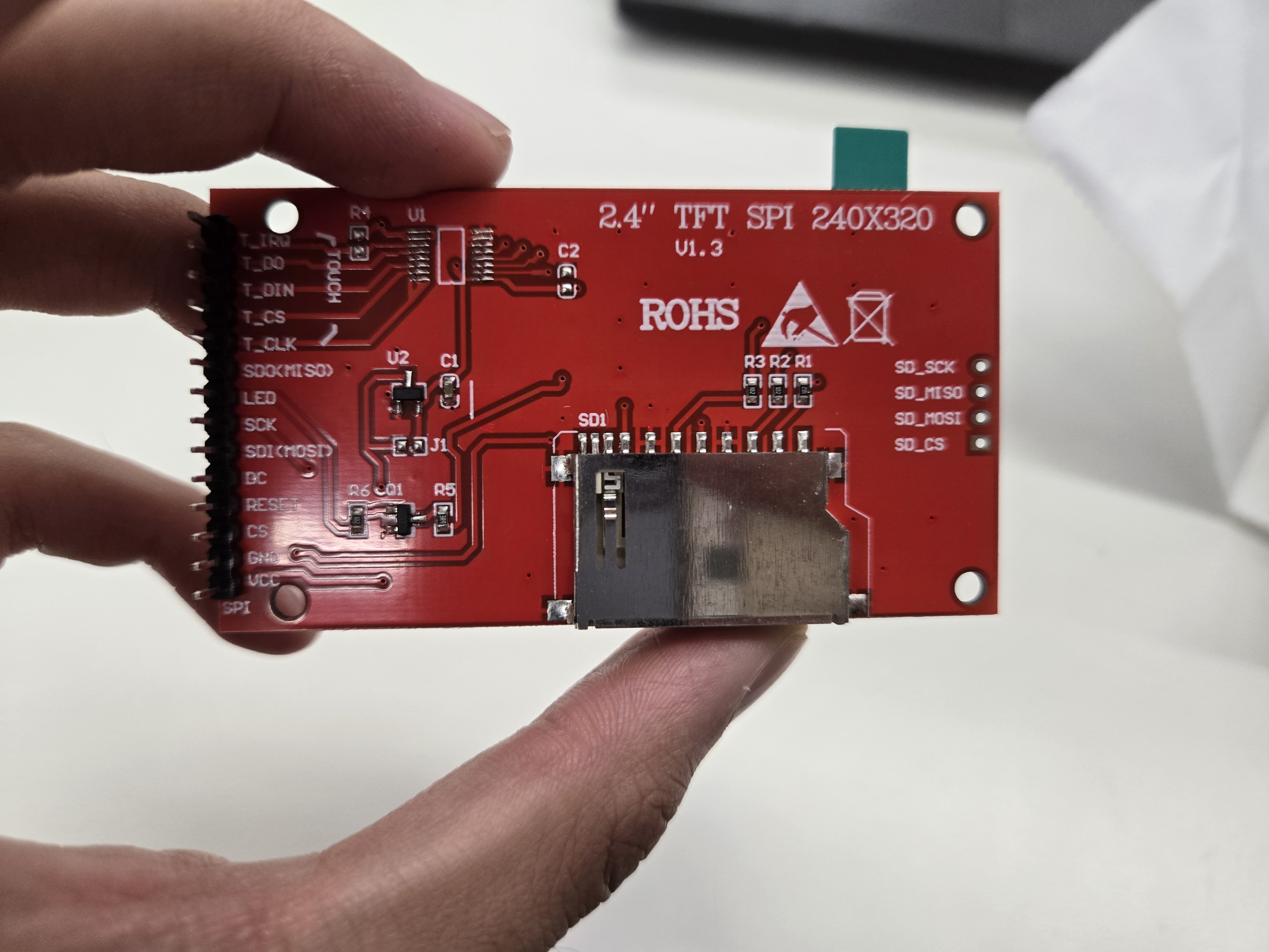
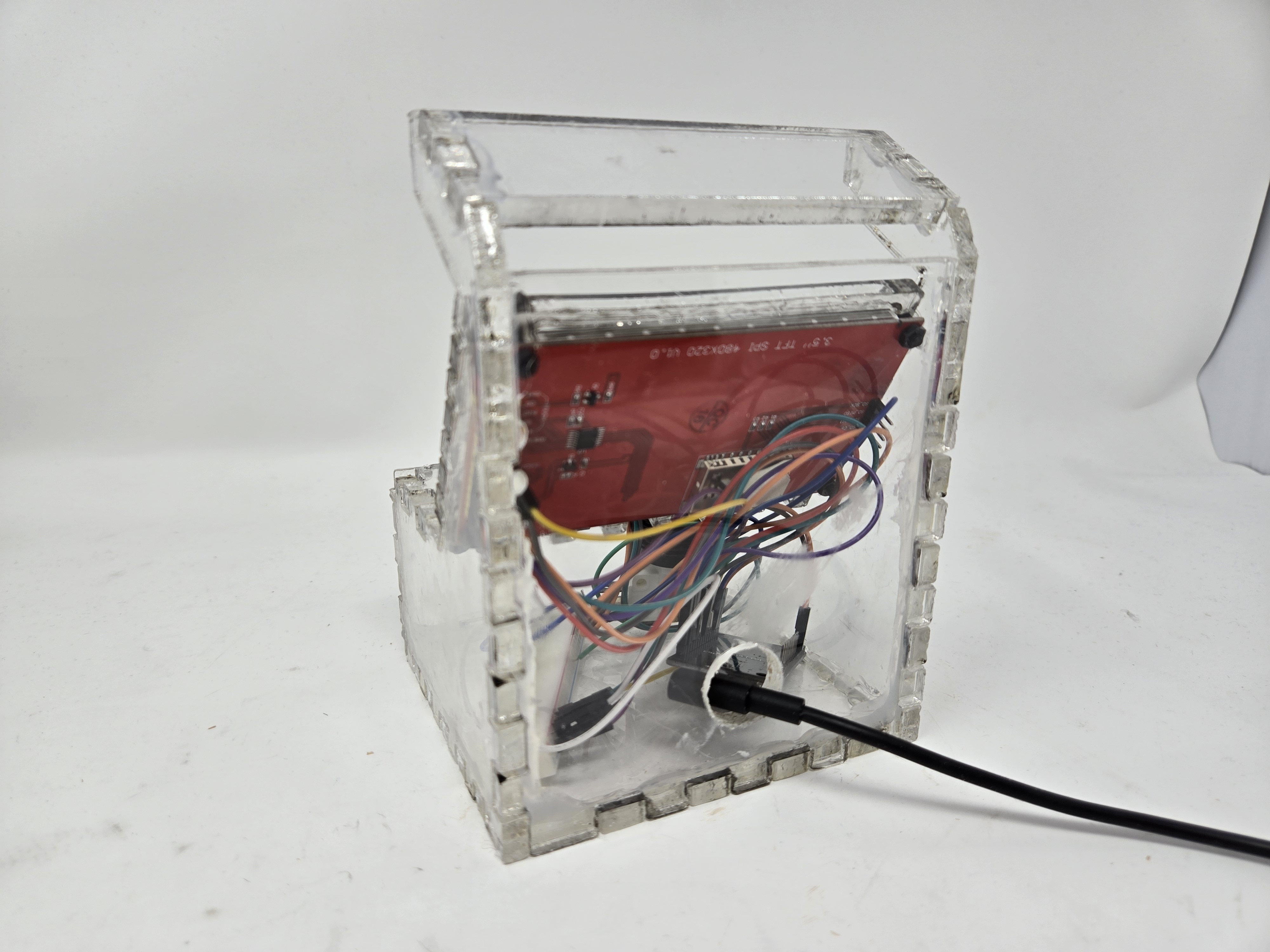
Back of the screen.
VCC: Power (VIN) GRND: ground lol (GRND) CS: Chip select – not relevant for this project since I’m only using one screen. (15) Reset: Pretty self explanatory too (4) DC: Data Command pin, used to send a lot of the SPI protocol for serial communication (2) SDI (MOSI): MOSI stands for master in slave out, which is used to send signals from the master controller (one screen) to potentially another screen. (23) SCK: Also a data clock line, used for serial communication synchronization. (18) LED: The backlight for the display. I had this wired to power because I wanted the backlight to always be on. (VIN) SDO/MISO: Opposite of MOSI, MISO stands for Master Out Slave In. (didn’t use)
Here’s also a reading of the SCK pin, used for serial synchronization. It seems that the clock line pulses every four seconds, which makes sense that it would have a regular pulse for its function as a clock. After reading some more documentation online, the SCK line is used for synchronization data transmission.
The other component necessary for playing these games was a joystick. This was a lot simpler to deal with, as the joystick has a much more simple and intuitive set of pins. I’ve taken apart game controllers in the past and so had a pretty good understanding of how this worked. Essentially, a joystick takes separate x and y inputs along its 2d plane of motion and translates those inputs into the computer. Below is another short description of that:
GRND: See above (GRND) +5V: Same deal as VCC, used for power (VIN) VRx: Takes inputs from the joystick moving in the x direction. (34) VRy: Takes inputs from the joystick moving in the y direction. (35) SW: Used for the button underneath the joystick – not relevant to my project but a cool feature (n/a)
With that all wired up to a breadboard (correctly), the next task was the software. I originally wanted to use emulation software that would allow me to take ROM hacks (semi non legal versions of old games available on the internet) and play them on my machine, but after days of Bobby and I running into issues with software compatibility, outdated code and databases, I decided to make my own simple game that was more within the scope of this project. I ended up modifying one of the example programs for a pong clock by adding in the ability to control the paddle. Through this, I gained a great appreciation (and frustration) for the amount of work necessary to program a TFT screen. Because the 2.4” TFT screen I was using had slightly different drivers from other ones online, I had to figure out the specifics of the code by myself. While not my strongest suit, I eventually figured it out and was able to get the game to work:
At this stage, the joystick is really sensitive to input and gets stuck at the bottom of the screen. Furthermore, because of the way that the game was originally coded, the ball would fly off the screen and never come back, so I had to code in a way for the ball to keep bouncing off the edges of the screen to stay in bounds. That’s it for the MVP part of the project!
Final Project Update
Note: Because I did my MVP late, this was essentially the next day of work in the lab.
After getting the screen to successfully work, I started to design the housing for the cabinet. I wanted to avoid 3d printing as much as possible because prototypes take significantly longer than laser cuts and are sometimes not as strong. To get a good sense of how the brain (the parts) would fit into the body, I modeled and cut out a few test cuts to see how precise the placement of the holes needed to be to accommodate the parts I wanted to use. When I cut the parts out of cardboard, the tolerances were surprisingly tight, so I was able to model the housing pretty close to the measurements of the parts.
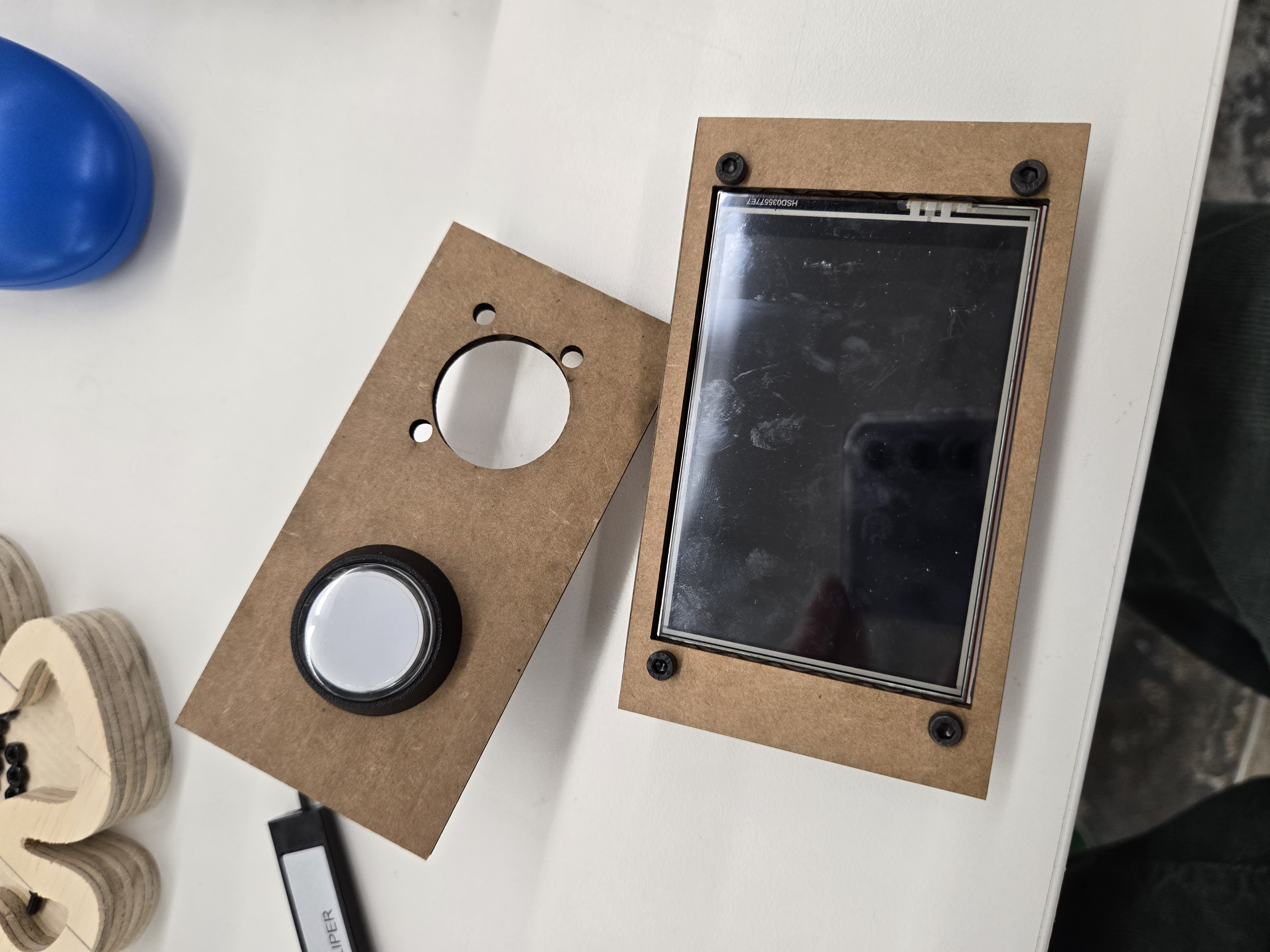
Test mount of key components.
To design the 3d model, I imported the parts into fusion and drew out what I thought the cabinet should look like. Because these were fairly common components, I was able to find the parts easily on Grabcad (https://grabcad.com/dashboard) and import them into fusion. The 3d model looked like this:
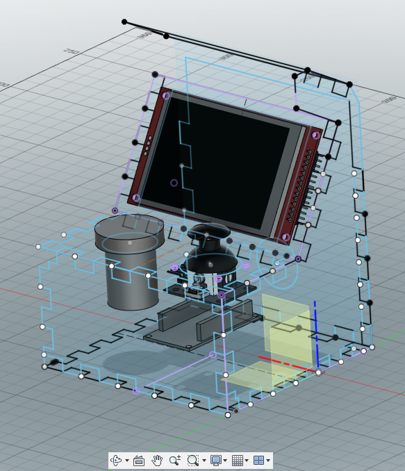
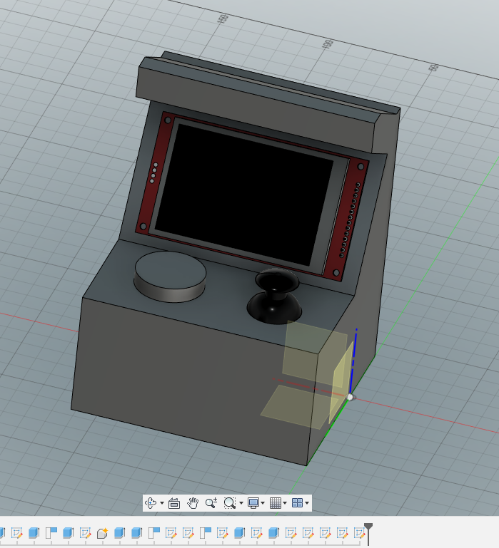
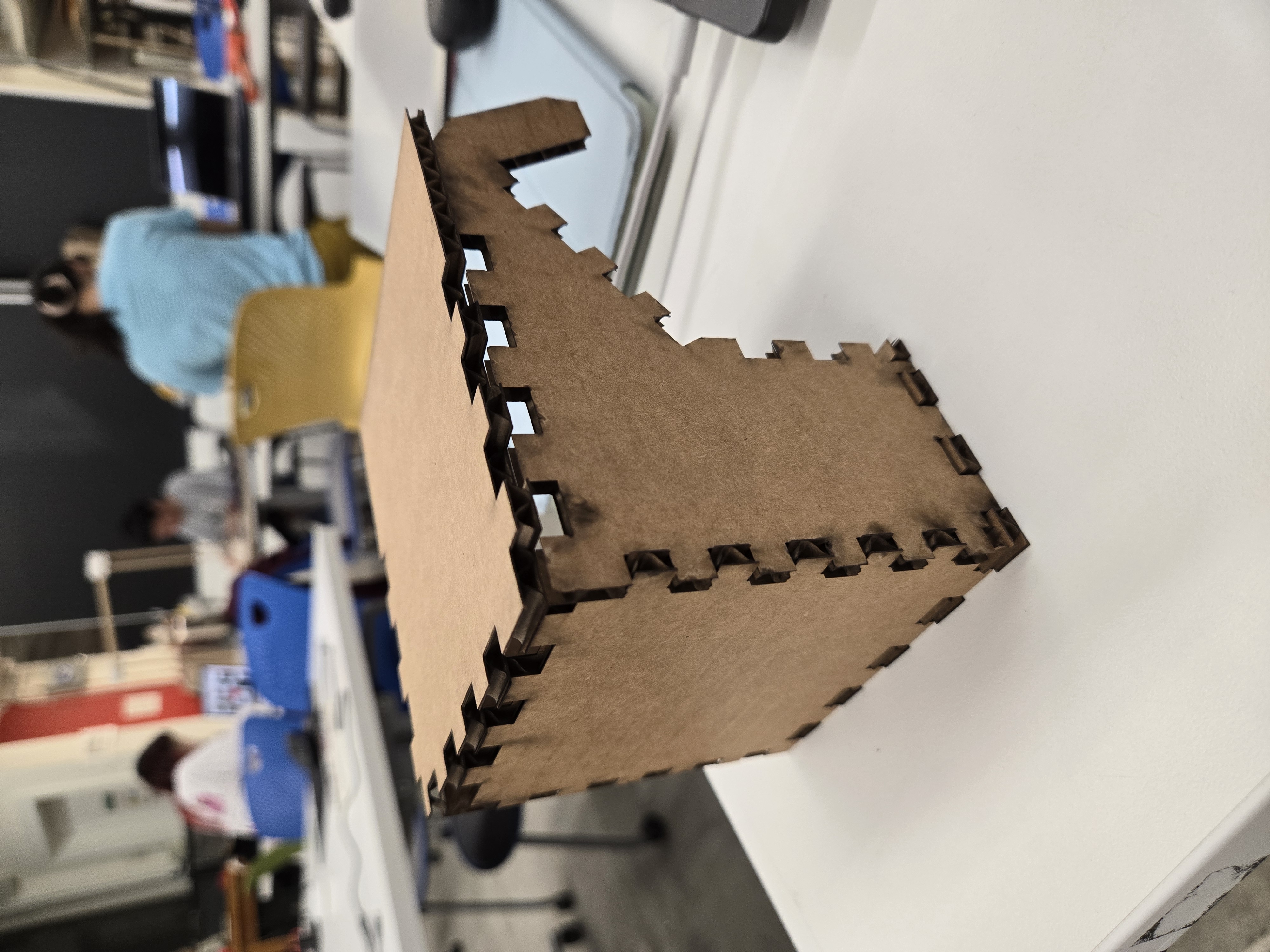
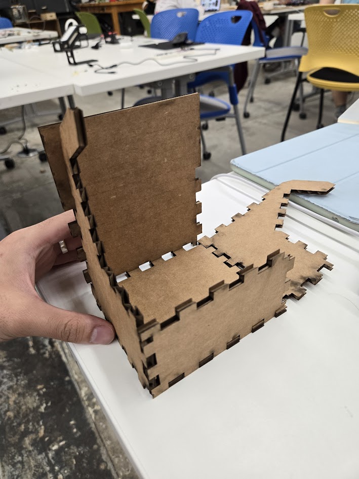
Putting the models in was quite helpful in determining how to design the proportions of the machine. It also made the next step, which was designing each of the sketches of all the faces of the cabinet to be laser cut, much easier. With a simple shape, like a box, I could get away with just looking at diagrams online of how boxes lay flat and pretty easily understand the basic layout. However, with the screen mount at an angle, the button mounts, and the overall more complex nature of the cabinet, the model in fusion was instrumental in not going crazy when modeling. To do this, I created sketches along each of the faces and took into account the thickness of the material I was using when designing the teeth. The non-parallel edges are not the same length or proportions, so I had to manually calculate the appropriate spacing and side of the teeth for each component. Because of these heterogeneous sides, the corners of each side had a puzzle piece-like structure in order to accommodate the two different teeth sizes coming together, which was quite the challenge. It also meant that the cabinet could only fit together in a certain configuration, which was a challenge for assembly. Here are a couple of the cardboard prototypes that I created to test the teeth fit.
The next step was cutting the pieces out of clear acrylic. This presented its own set of issues – the plastic would often melt in unexpected ways and the pieces would warp after the cut. Furthermore, the laser residue would get on the pieces and cause it to become cloudy and have a permanent burnt look. While this is an aesthetic for some, I wanted to have a clear cabinet. I found that by cutting the acrylic with the protective film on top, I was able to get a much cleaner cut.
Once all the pieces were cut, I was able to assemble the housing! Here is the before and after of the peel:
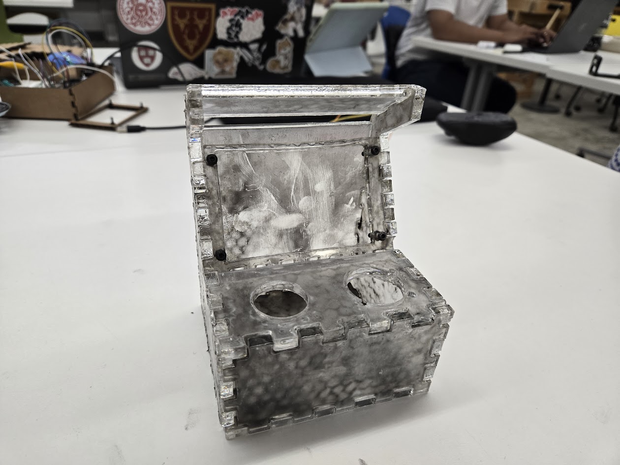
So happy with the results!
Final Final Project Update: Assembly
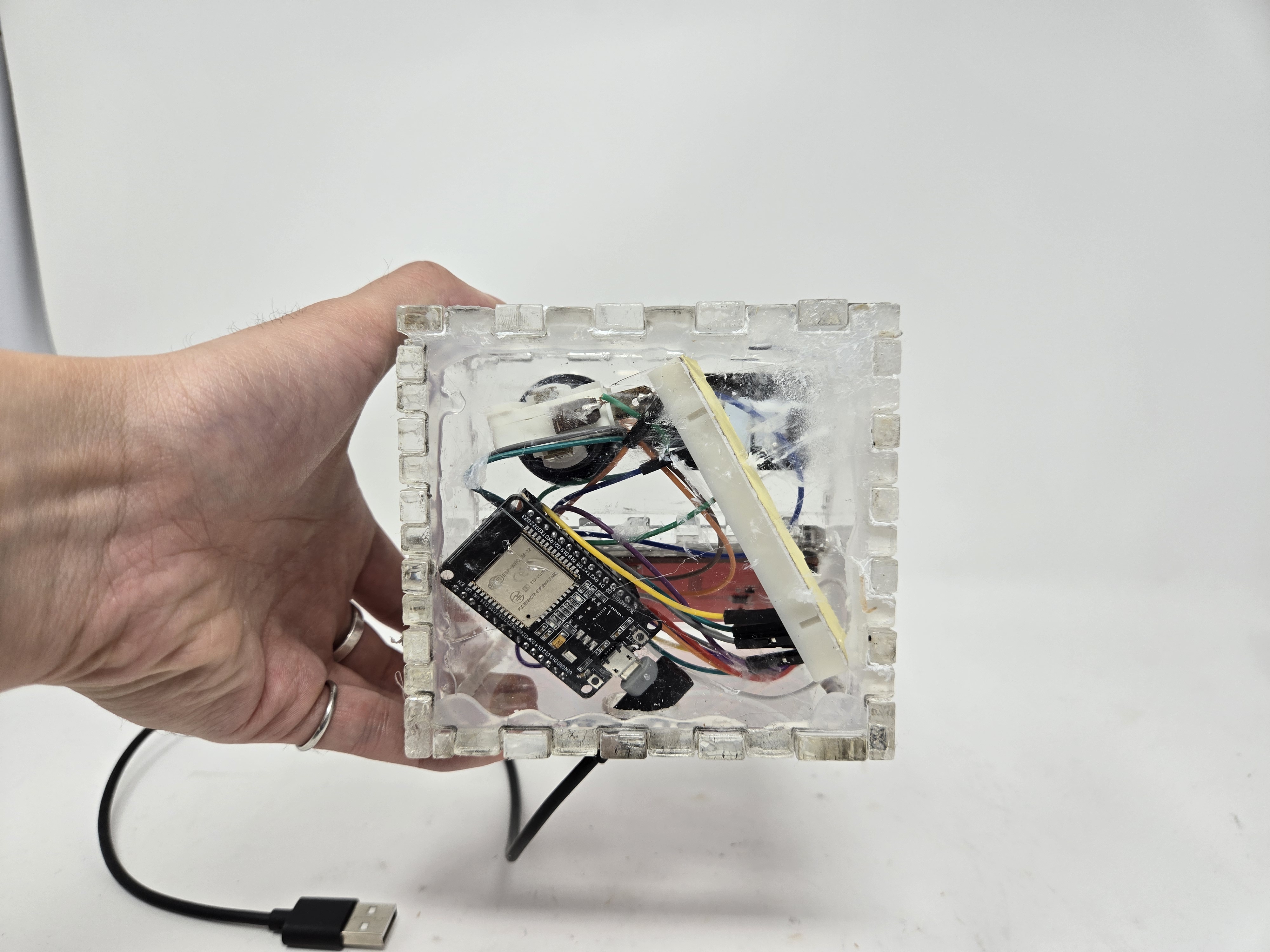
Finally, it was time to put it all together. First, I test fit all the parts into the housing. While the cardboard parts had fit earlier, some of the imperfections in the laser cut caused some of the elements not to fit correctly. As a result, I had to recut a couple pieces and ended up cracking a few while trying to remove them from the acrylic. Once all the components fit, I ran a quick test program with the components off the breadboard to test if they worked:
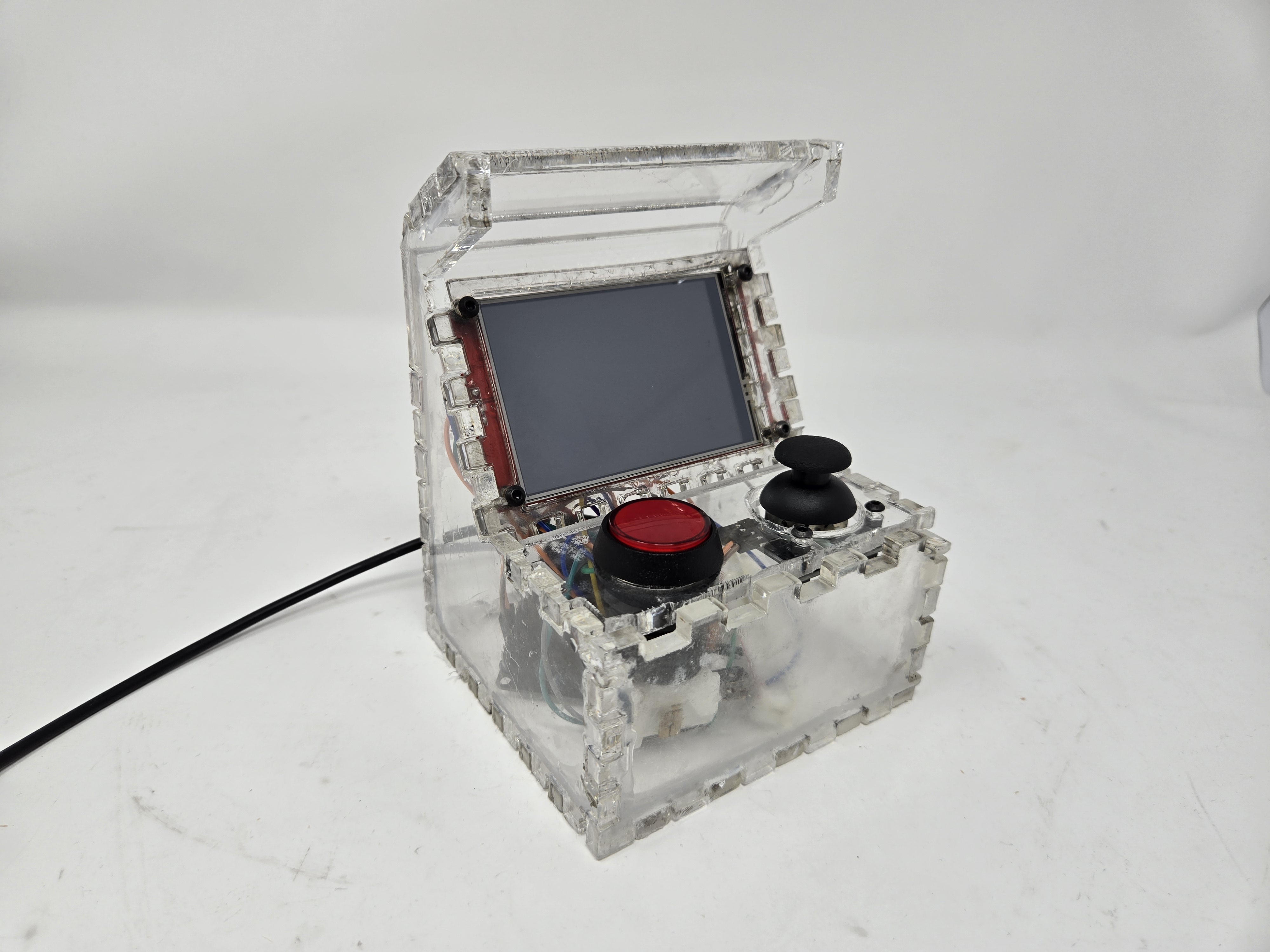
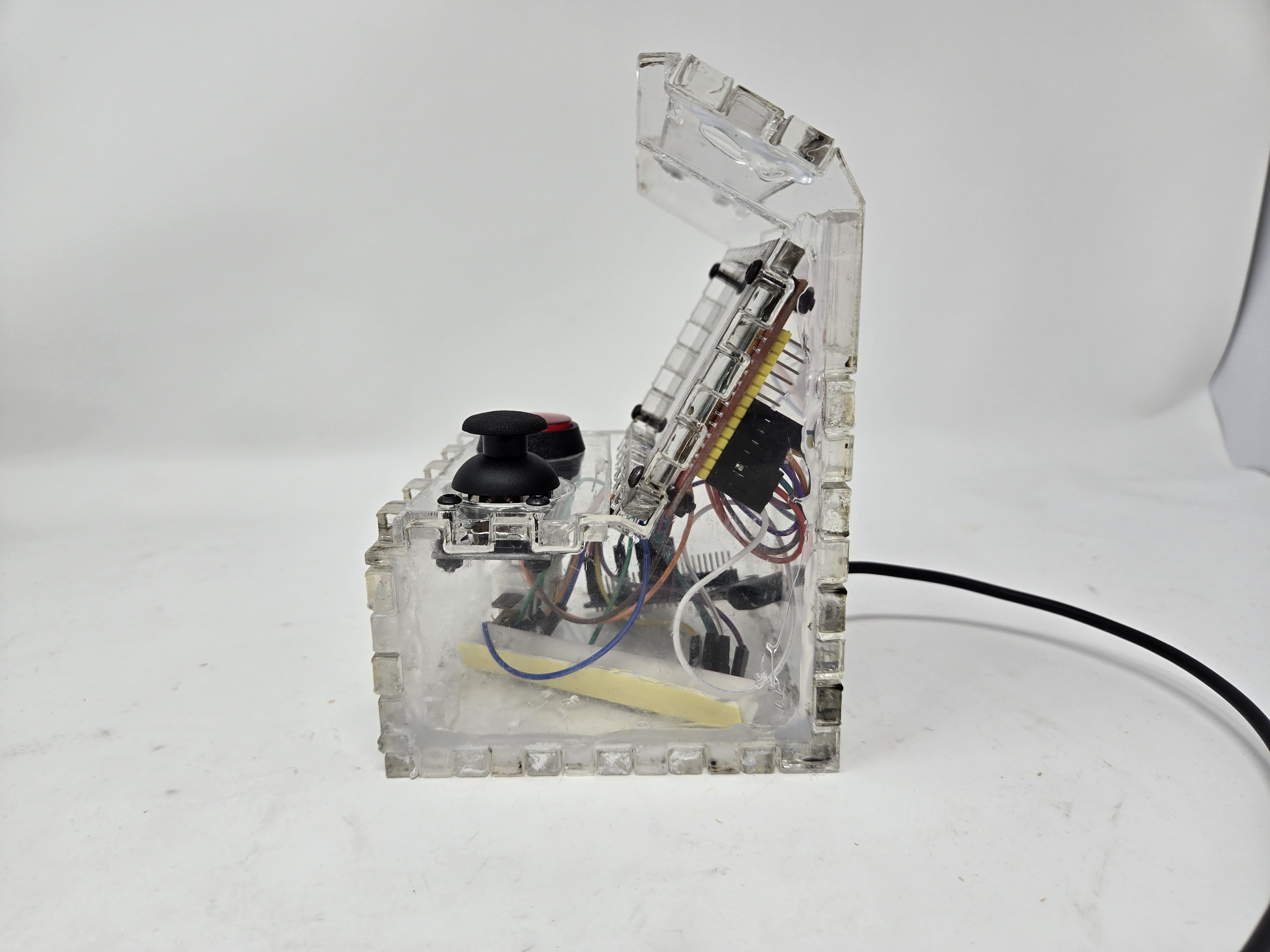
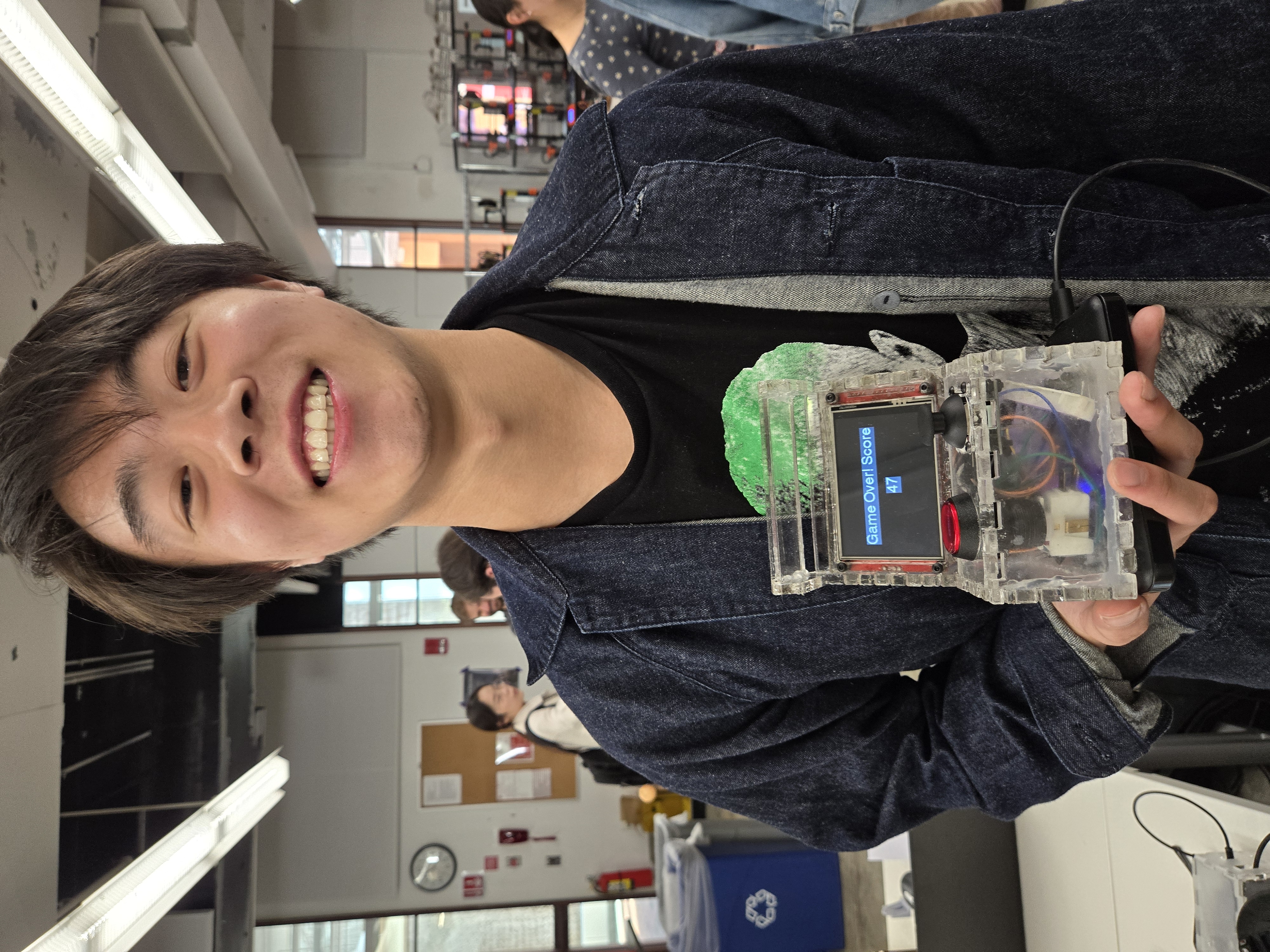
After all the components worked together, I put the whole thing together and marveled at how well it turned out. After a few tries the housing was perfect and I was really happy with how the transparent panels showed off all the electronics inside. I also used a big red button from a larger array of buttons to reset the game. And because it looks awesome. Here are some nice product shots of the cabinet:
I also worked on adding a score counter and changing the mechanics of the game. The 6 x 6 pixel ball was a bit too small, so for demonstration purposes, I increased the size to 18 x 18 and made the paddles larger. The game works by starting the ball off on the player’s side (left) launching towards the computer side (right). Whenever the ball makes contact with the paddle, it chooses a random speed and angle to launch at and reverses direction. It also leaves a trail once the ball moves at its max speed for a cool particle effect. Finally, when a player loses by having the ball touch the left side of the screen, the game over screen appears with the player’s score. To play again, the big red button resets the game and queues up the system for another try!
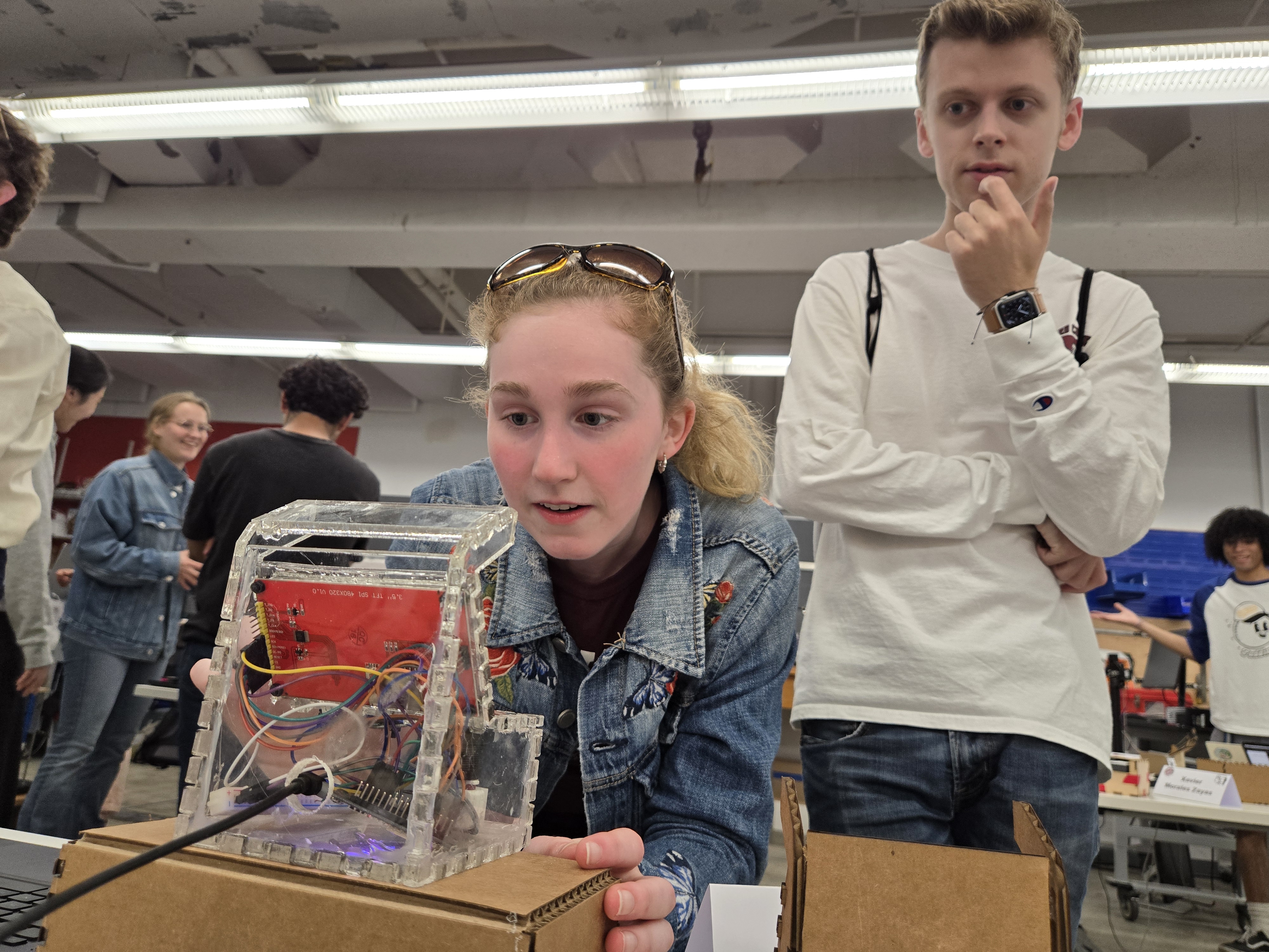
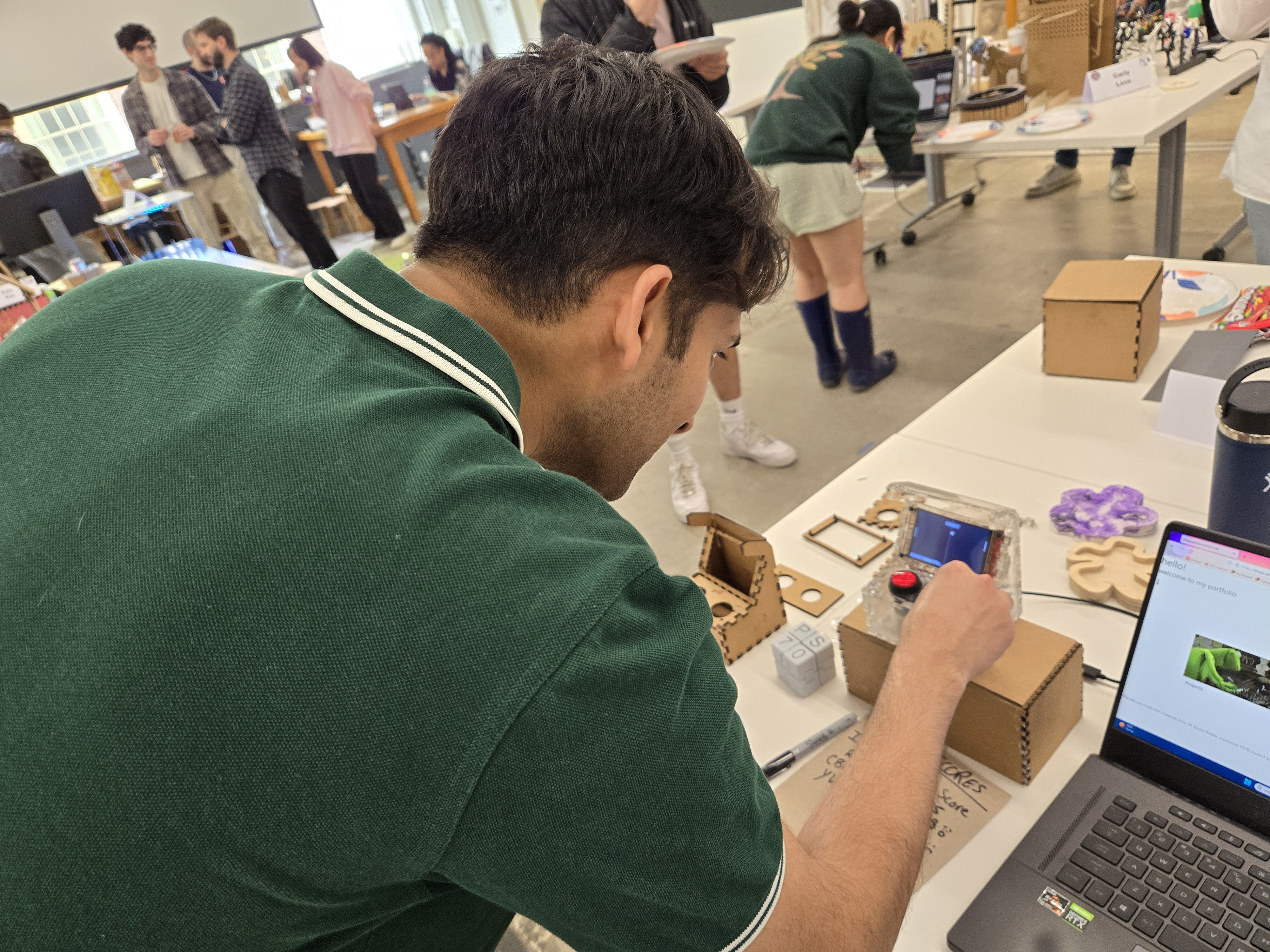
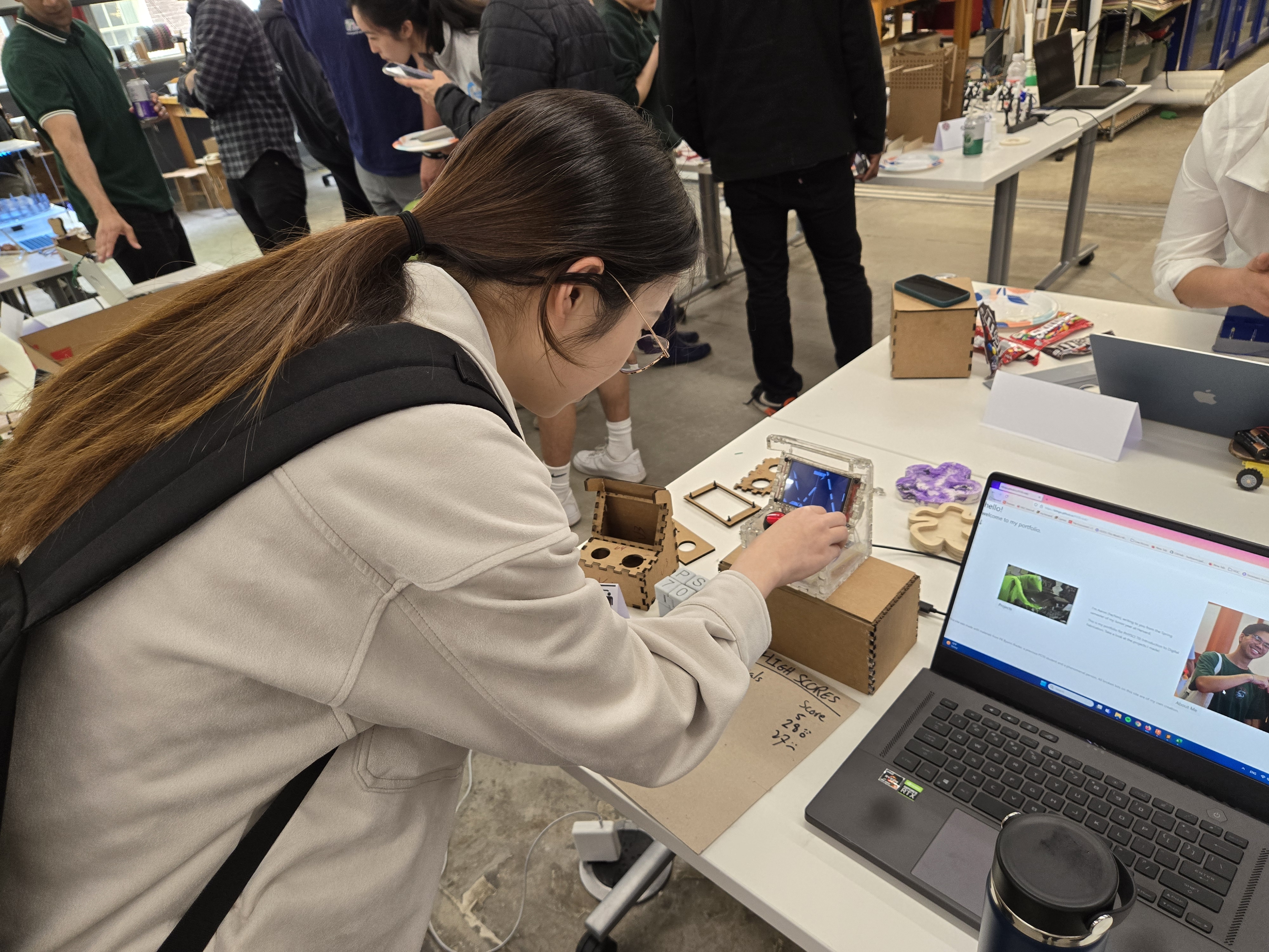
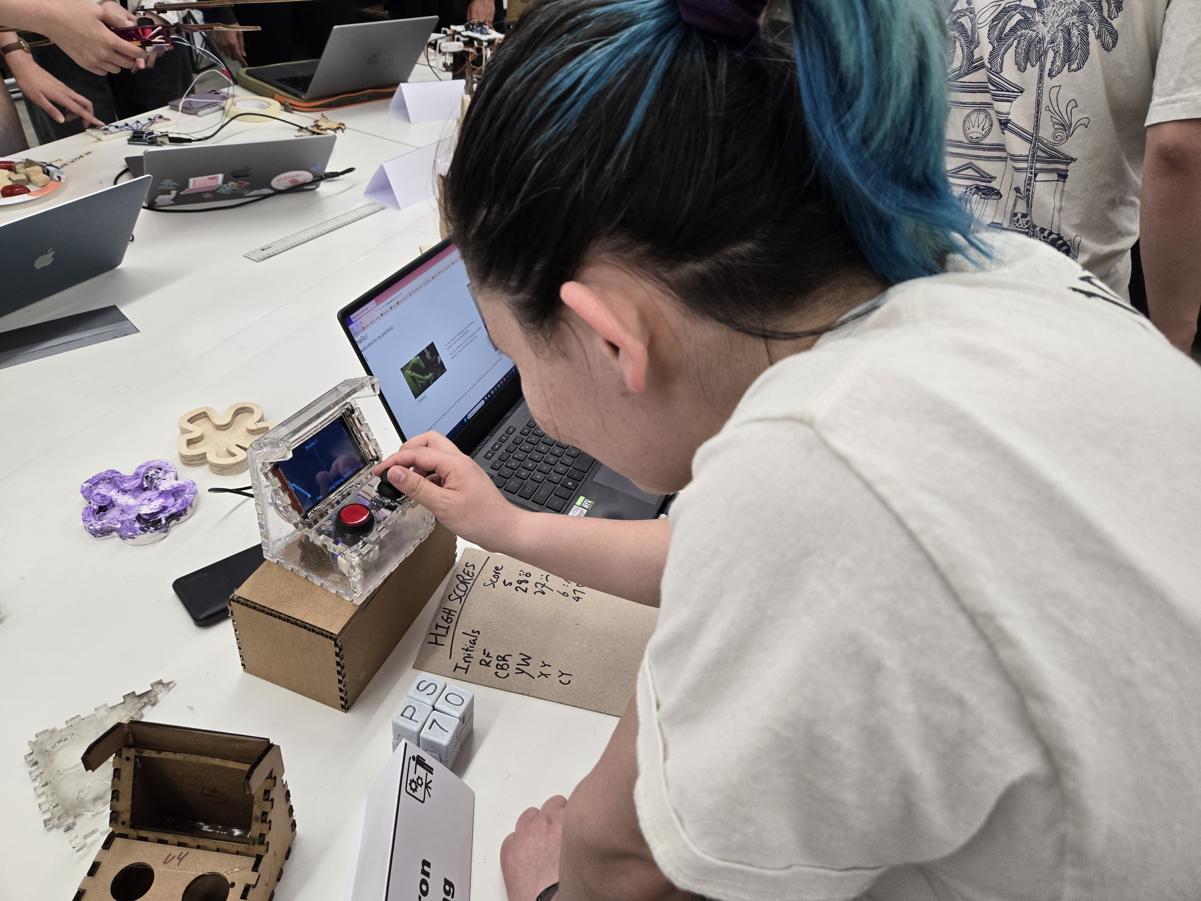
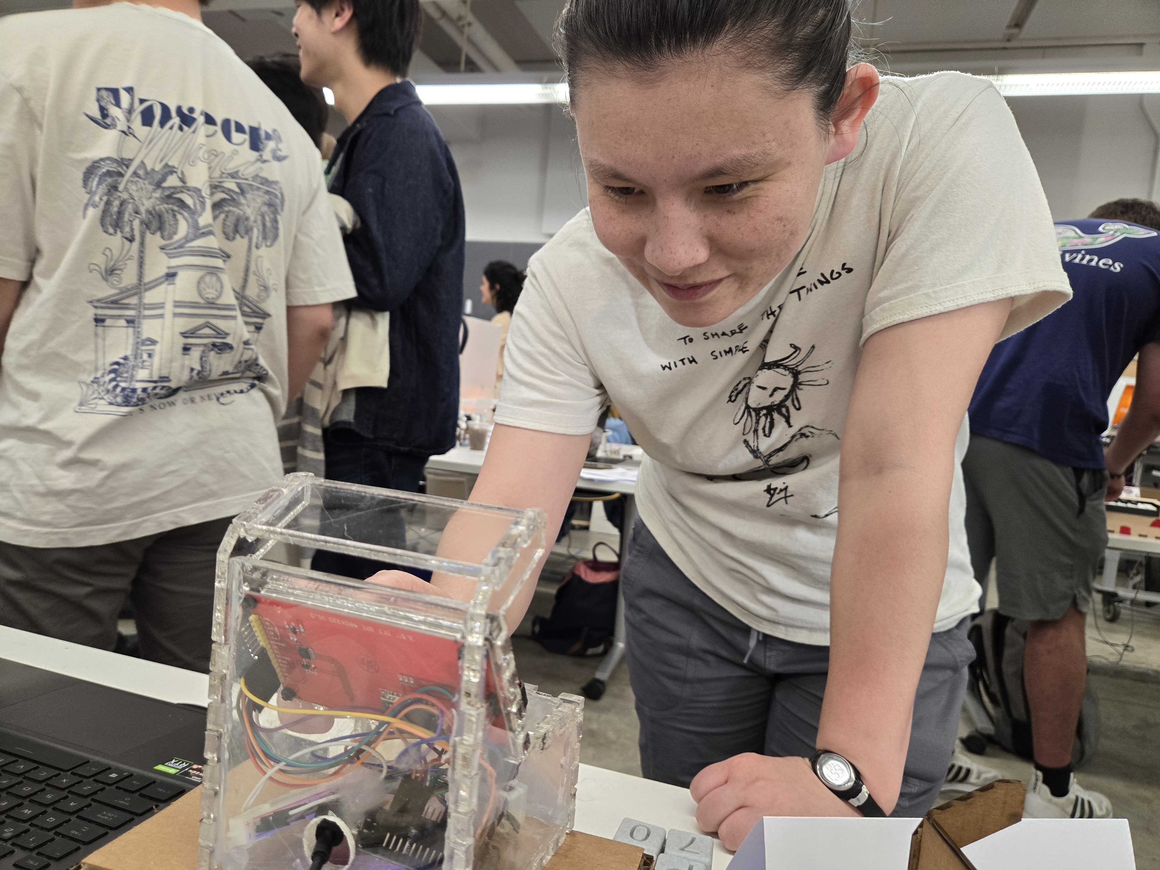
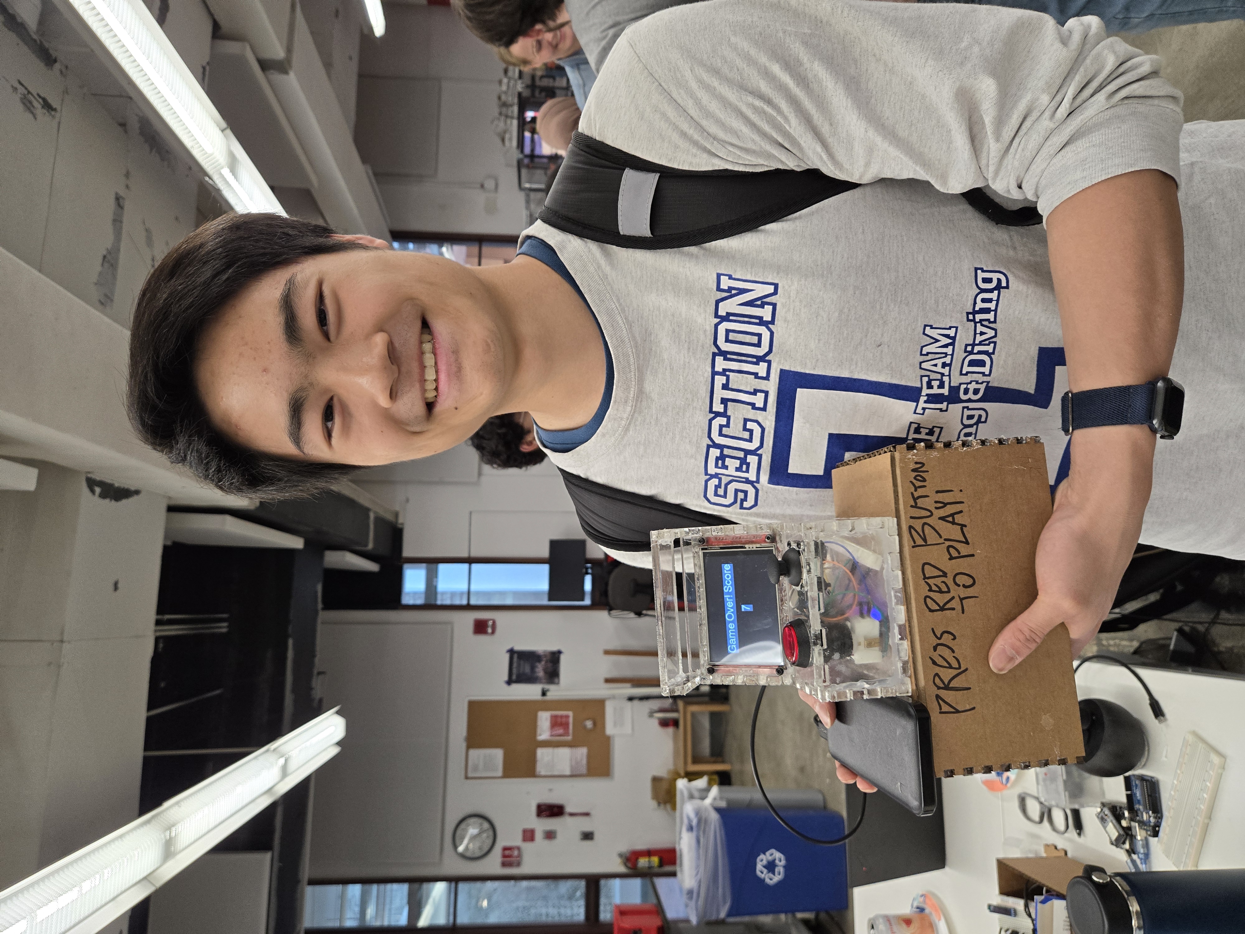
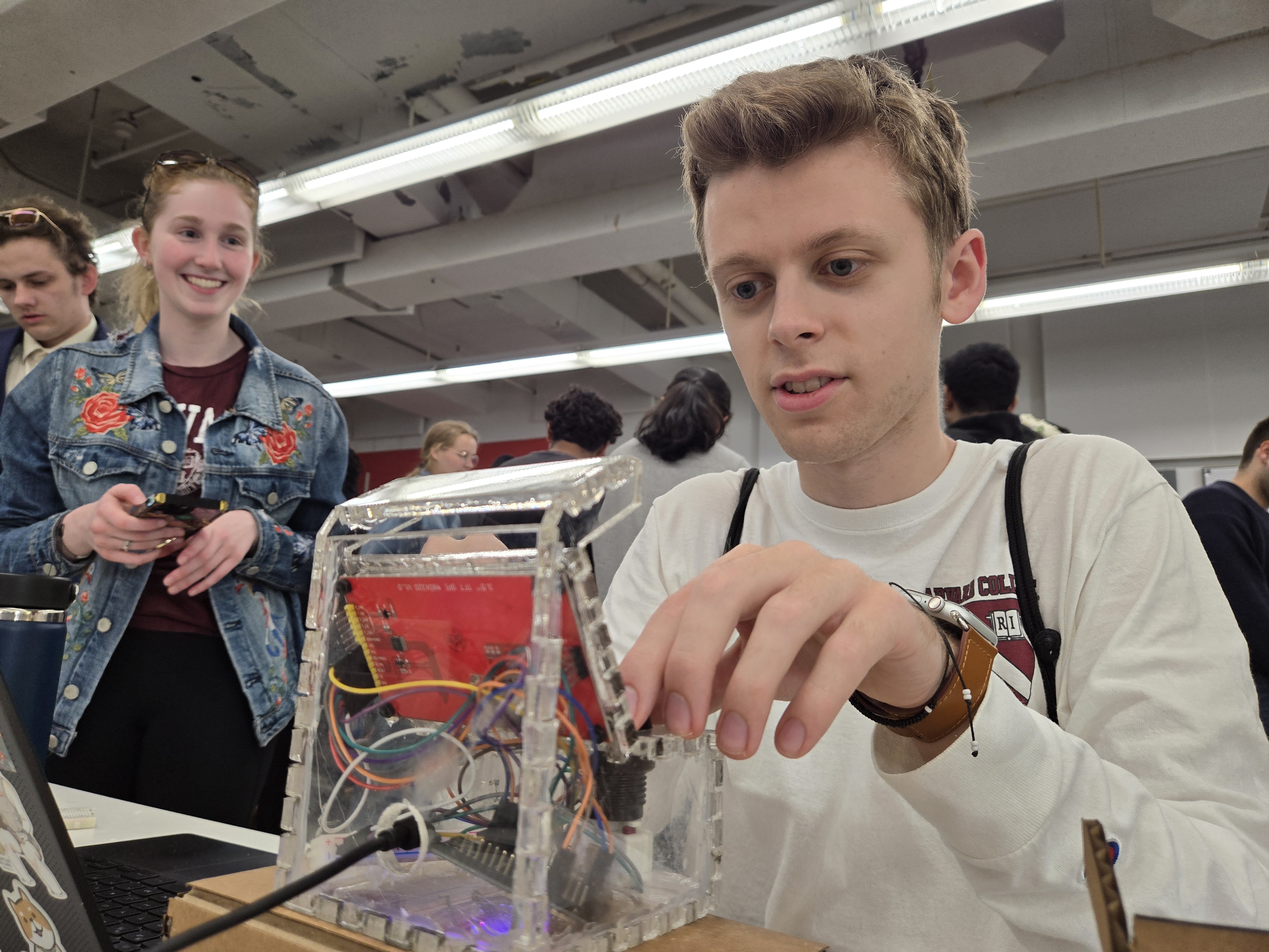
Here are some photos of people having fun with it at the final project fair:
Overall I loved designing and executing this project. This will be a permanent mainstay desk ornament and fun conversation starter for whomever enters my dorm. Major shoutouts to Bobby and Kassia for helping me slog through all the Arduino code and various “where is this in the shop” questions. That’s it for now! Onto senior year :)